

The Manthorpe Flash Abutment Vent is a simple one-piece roll-out, an easy fit sheet that provides ventilation for abutment roof details, providing a weather-tight solution to the need for a continuous 5mm² of airflow.
Fitting Instructions
ll abutment flashings require the lead to be dressed a minimum of 150mm down the top course of slates or roof tiles. This distance increases for pitches below 30° and in areas with high exposure to severe weather conditions.
For roof pitches below 20º and in areas of high exposure, two rolls of flash vent may need to be joined together to provide a lap of sufficient length between the lead flashing and the tiles. This is achieved by pressing together the front edges of two rolls.
Step 1
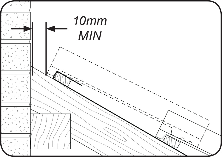
To achieve the required 5mm² air flow, fit the top roof batten to provide a 10mm gap between the back of the top row of tiles and the wall. The felt must then be returned around the top batten.
Step 2
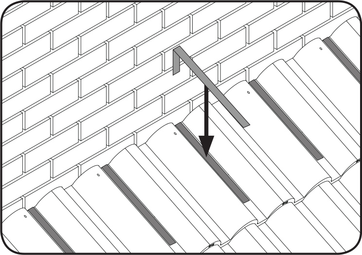
Remove the backing tape from the clips provided and hook the over the top row of tiles at 300mm centres (ensuring that the tiles are clean and dry). Bend the short leg of the clip round under the batten. Additional clipping may be required depending on the level of exposure as per Lead Sheet Association (L.S.A.) recommendations.
Step 3
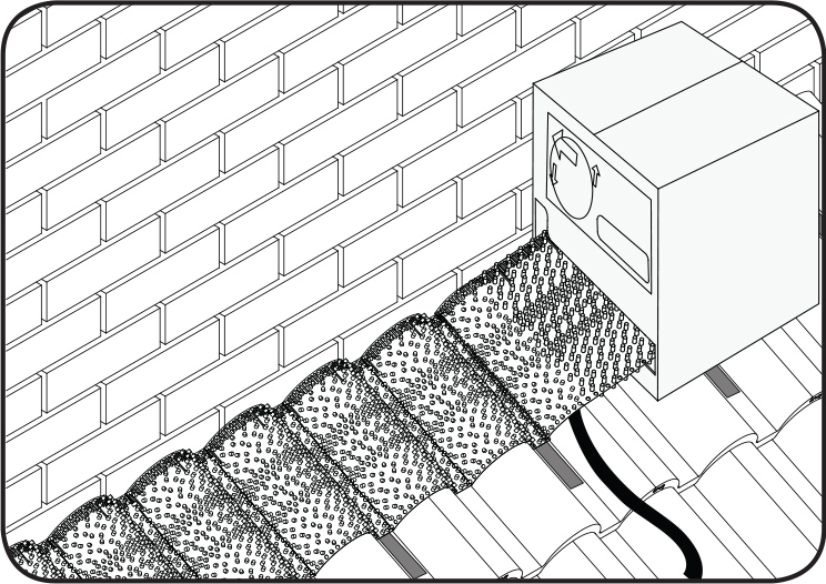
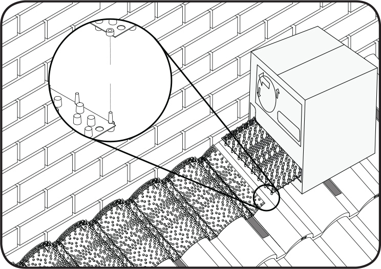
Tear open the perforation at the base of the box and pull out the start of the roll. Position the long pins against the back face of the top row of tiles as shown in the image above.
Step 4
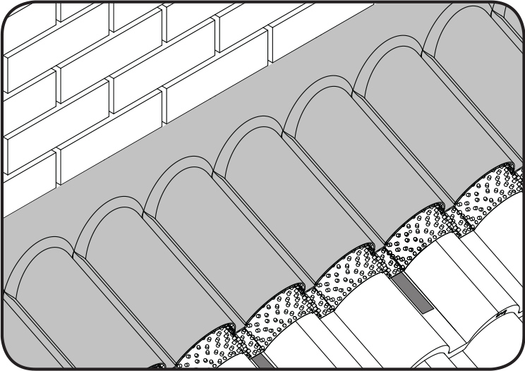
Moving across the roof from left to right, roll the flash vent out onto the tiles removing the backing tape from the mastic strip and firmly pressing it down onto the tile profile as you go.
Step 5
At the end of the abutment cut off any excess roll with a sharp knife. If one roll is not sufficient to complete the run of the abutment then additional rolls can be joined together by clipping the end of one roll to the start of the next as shown in the image above.
Step 6
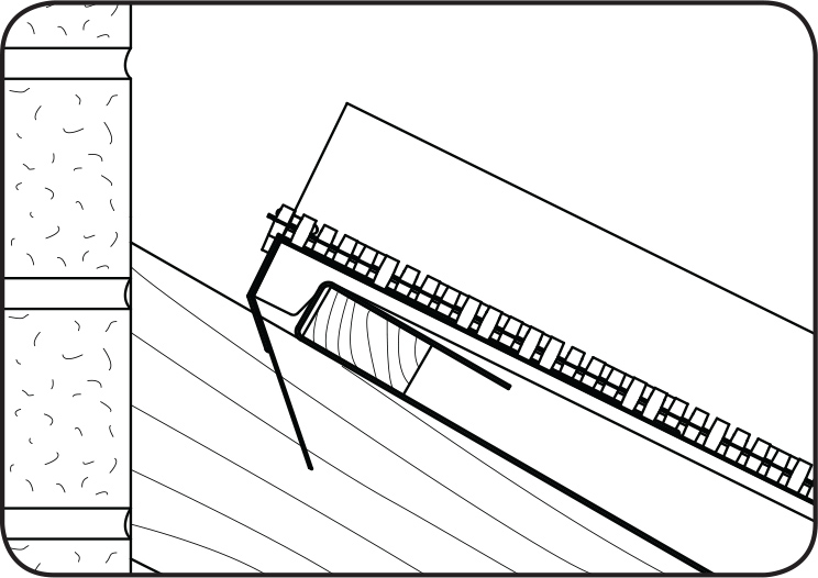
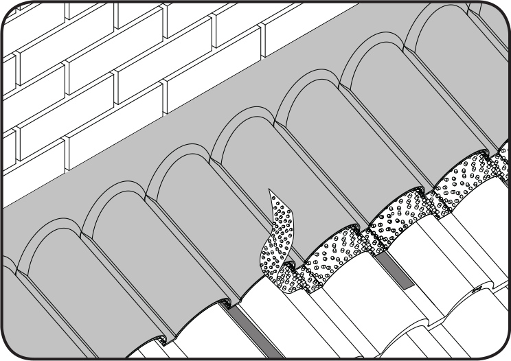
Dress the lead over the flash vent and tiles using standard lead working practices as recommended by the L.S.A. Ensure that the lead is dressed down beyond the upper indicator line of “trim
to suit lead” moulded on the vent.
Step 7
Using a sharp knife, cut away any excess flash vent which is protruding from the front edge of the lead.
Step 8
Finally, bend the clips over the clips over the lead ensuring that they are firmly pressed into position (any excess clip may be trimmed to length).